SimpleBot Shield Assembly: Difference between revisions
| (18 intermediate revisions by 2 users not shown) | |||
| Line 1: | Line 1: | ||
= SimpleBot Shield Assembly = | = SimpleBot Shield Assembly = | ||
The SimpleBot shield has a small number of through-hole components | The SimpleBot shield has a small number of through-hole components to be soldered on. The parts you need are: | ||
[[File:SimpleBot | [[File:SimpleBot-shield-parts.jpg|800px]] | ||
* 5x Screw terminal | * SimpleBot Shield with WS2812B RGB LEDs and capacitors pre-fitted. | ||
* | * 5x Screw terminal header blocks (mounted as one 4-way terminal and one 6-way terminal). | ||
* 4 pin female header for Ultrasonic Range Sensor | * Pin headers for Arduino shield mounting and hobby servo "motor" connections. | ||
* 4-pin female header for Ultrasonic Range Sensor. | |||
* 2x Electrolytic capacitors for the VIN & 6V power rails. | * 2x Electrolytic capacitors for the VIN & 6V power rails. | ||
* LDR | * LDR (light dependent resistor) and fixed resistor for ambient light sensing. | ||
* 6V linear regulator for servo power supply (most hobby servos run much better at 6V than at 5V). | * 6V linear regulator for servo power supply (most hobby servos run much better at 6V than at 5V). | ||
== Soldering Arduino Headers == | == Soldering Arduino Headers == | ||
To solder the Arduino headers, it's easiest to use an Arduino-compatible board as a "jig". Start by mounting the | To solder the Arduino headers, it's easiest to use an Arduino-compatible board as a "jig" to keep the headers straight while they are being soldered. Start by mounting the PiLeven on top of the Raspberry Pi, as shown: | ||
[[File:PiLeven on Pi.jpg|400px]] | [[File:PiLeven on Pi.jpg|400px]] | ||
The male pin headers are supplied cut to the correct length to match each header on the PiLeven: | |||
* 2x 8-pin headers | * 2x 8-pin headers | ||
| Line 24: | Line 25: | ||
* 1x 6-pin header | * 1x 6-pin header | ||
Place them into the PiLeven headers as shown: | |||
[[File:PiLeven with headers.jpg|400px]] | [[File:PiLeven with headers.jpg|400px]] | ||
Slip the SimpleBot Shield onto the headers so it sits in place on the PiLeven: | |||
[[File:PiLeven with SimpleBot shield in place.jpg|400px]] | [[File:PiLeven with SimpleBot shield in place.jpg|400px]] | ||
| Line 36: | Line 37: | ||
[[File:PiLeven Arduino headers soldered.jpg|400px]] | [[File:PiLeven Arduino headers soldered.jpg|400px]] | ||
After you've soldered the headers, remove the SimpleBot shield from the PiLeven. | After you've soldered the headers, remove the SimpleBot shield from the PiLeven. The headers should all be straight. | ||
== Screw Terminals == | == Screw Terminals == | ||
| Line 46: | Line 47: | ||
The SimpleBot shield has one side with 6 pins (3 units), and one side with 4 pins (2 units). | The SimpleBot shield has one side with 6 pins (3 units), and one side with 4 pins (2 units). | ||
Slot the terminals together and place them on top of the shield: | Slot the terminals together and place them on top of the shield back to back, with the terminal openings facing out: | ||
[[File:SimpleBot screw terminals on top of shield.jpg|400px]] | [[File:SimpleBot screw terminals on top of shield.jpg|400px]] | ||
Then use some Blu- | Then use some Blu-Tac or your finger to hold them down so you can flip the shield over and solder the pins from the bottom: | ||
[[File:SimpleBot screw terminals soldered.jpg|400px]] | [[File:SimpleBot screw terminals soldered.jpg|400px]] | ||
== Regulator & Capacitors == | == Voltage Regulator & Capacitors == | ||
Next step is to solder the 6V regulator and the electrolytic capacitors. | Next step is to solder the 6V regulator and the electrolytic capacitors. | ||
| Line 60: | Line 61: | ||
[[File:SimpleBot regulator and capacitors placed.jpg|400px]] | [[File:SimpleBot regulator and capacitors placed.jpg|400px]] | ||
All of these components need to be oriented correctly. Place the regulator as shown. | All of these components need to be oriented correctly, and can be damaged if you fit them backwards. Place the regulator as shown, with the large metal tab facing towards the screw terminals. | ||
Electrolytic capacitors have a grey stripe on the side marked "-", which is the '''negative''' side. The circuit board has a small plus marked next to the pin for the '''positive''' side. Both the positive sides face towards the regulator, as shown, so the capacitors are "mirrored" in orientation to each other. | Electrolytic capacitors have a grey stripe on the side marked "-", which is the '''negative''' side. The circuit board has a small plus marked next to the pin for the '''positive''' side. Both the positive sides face towards the regulator, as shown, so the capacitors are "mirrored" in orientation to each other. | ||
You can bend the pins on the capacitors and the regulator to make them stay in while you solder them, or use Blu- | You can bend the pins on the capacitors and the regulator to make them stay in while you solder them, or use Blu-Tac. | ||
[[File:SimpleBot regulator and capacitors bottom.jpg|400px]] | [[File:SimpleBot regulator and capacitors bottom.jpg|400px]] | ||
After they are soldered you can cut the leads off: | After they are soldered you can cut the leads off. Make sure you hold the lead while you cut it, so that it doesn't shoot off like a tiny metal javelin straight into your eye: | ||
[[File:SimpleBot regulator and capacitors trimmed.jpg|400px]] | [[File:SimpleBot regulator and capacitors trimmed.jpg|400px]] | ||
| Line 74: | Line 75: | ||
== LDR, Range Sensor Header, Servo Headers == | == LDR, Range Sensor Header, Servo Headers == | ||
Next step is the LDR ( | Next step is the LDR (light dependent resistor), the 4-pin female header for the Ultrasonic Range Sensor, and the two 3-pin male headers for the "Motors" (actually continuous rotation hobby servos, not normal motors). | ||
For the 3 pin headers, cut them from | For the 3 pin headers, cut them from longer male header strips if they haven't been pre-cut. | ||
Place the parts into the PCB as shown. Orientation doesn't matter with these parts. | Place the parts into the PCB as shown. Orientation doesn't matter with these parts. | ||
| Line 82: | Line 83: | ||
[[File:SimpleBot LDR and range header.jpg|400px]] | [[File:SimpleBot LDR and range header.jpg|400px]] | ||
It's recommended you leave LDR sitting high above the PCB surface, as shown, so you can bend it forwards 90 degrees to create a directional light sensor. | |||
The LDR can be soldered from the top or the bottom, but the header needs to be soldered from the bottom. Use Blu- | The LDR can be soldered from the top or the bottom, but the header needs to be soldered from the bottom. Use Blu-Tac or your finger to hold items in place when flipping the board. | ||
[[File:SimpleBot LDR and range header soldered.jpg|400px]] | [[File:SimpleBot LDR and range header soldered.jpg|400px]] | ||
| Line 90: | Line 91: | ||
== Wire AREF to 5V == | == Wire AREF to 5V == | ||
There's a flaw in the current SimpleBot Shield design | There's a flaw in the current SimpleBot Shield design: the LDR is connected to the "AREF" pin on the shield when it should be connected directly to "5V". | ||
To fix this problem, solder a | To fix this problem, solder a quick fix from the AREF pin on the shield to either the "5V" pin or the "IORef" pin on the shield. You can use the wire wrap wire in the kit, or the cut off leg of a resistor or another component. | ||
[[File:SimpleBot AREF Fix.jpg|400px]] | |||
Once you've done this, cut off the "AREF" pin on the shield to disconnect from AREF on the PiLeven: | |||
[[File:SimpleBot AREF Pin Cutoff.jpg|400px]] | |||
[[File:SimpleBot AREF Pin Cut 2.jpg|400px]] | |||
== Reset Button & Resistor == | == Reset Button & Resistor == | ||
The | The 10k resistor forms a [https://en.wikipedia.org/wiki/Voltage_divider voltage divider] with the LDR in order to output a voltage proportional to the ambient light level. | ||
Bend the leads of the resistor so that it slips neatly into the holes on the PCB: | |||
[[File:SimpleBot-resistor-bent.jpg|240px]] | |||
The resistor and the reset button can be soldered from the top or the bottom, as you prefer. If soldering the reset button from the top, take care not to melt the plastic body of the button. | The resistor and the reset button can be soldered from the top or the bottom, as you prefer. If soldering the reset button from the top, take care not to melt the plastic body of the button. | ||
| Line 108: | Line 117: | ||
== All Done == | == All Done == | ||
All done! As a final check, look over the shield for any solder bridges and also double-check the | All done! As a final check, look over the shield for any solder bridges and also double-check the that the regulator and the electrolytic capacitors aren't installed backwards: | ||
[[File:SimpleBot shield assembled.jpg|400px]] | [[File:SimpleBot shield assembled.jpg|400px]] | ||
| Line 117: | Line 126: | ||
Next step, you can move on to [[SimpleBot Chassis Assembly]]. | Next step, you can move on to [[SimpleBot Chassis Assembly]]. | ||
[[SimpleBot-Assembly|Back to SimpleBot Assembly Overview]] | |||
Latest revision as of 23:05, 12 January 2015
SimpleBot Shield Assembly
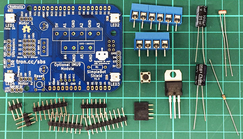
The SimpleBot shield has a small number of through-hole components to be soldered on. The parts you need are:
- SimpleBot Shield with WS2812B RGB LEDs and capacitors pre-fitted.
- 5x Screw terminal header blocks (mounted as one 4-way terminal and one 6-way terminal).
- Pin headers for Arduino shield mounting and hobby servo "motor" connections.
- 4-pin female header for Ultrasonic Range Sensor.
- 2x Electrolytic capacitors for the VIN & 6V power rails.
- LDR (light dependent resistor) and fixed resistor for ambient light sensing.
- 6V linear regulator for servo power supply (most hobby servos run much better at 6V than at 5V).
Soldering Arduino Headers
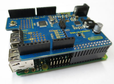
To solder the Arduino headers, it's easiest to use an Arduino-compatible board as a "jig" to keep the headers straight while they are being soldered. Start by mounting the PiLeven on top of the Raspberry Pi, as shown:
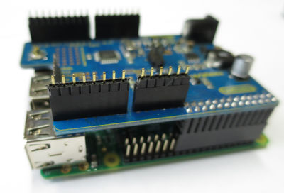
The male pin headers are supplied cut to the correct length to match each header on the PiLeven:
- 2x 8-pin headers
- 1x 10-pin header
- 1x 6-pin header
Place them into the PiLeven headers as shown:
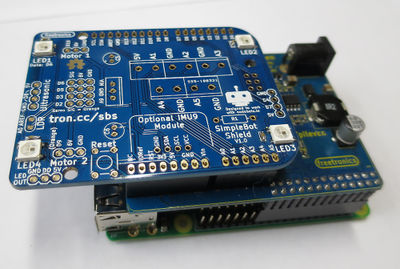
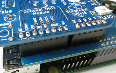
Slip the SimpleBot Shield onto the headers so it sits in place on the PiLeven:
Then solder them in place:
After you've soldered the headers, remove the SimpleBot shield from the PiLeven. The headers should all be straight.
Screw Terminals
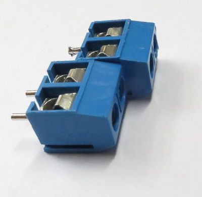
The next items to solder are the screw terminals. Each individual 2-pin screw terminal can slot together into a longer unit, like this:
The SimpleBot shield has one side with 6 pins (3 units), and one side with 4 pins (2 units).
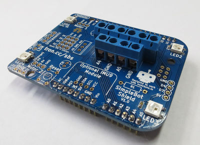
Slot the terminals together and place them on top of the shield back to back, with the terminal openings facing out:
Then use some Blu-Tac or your finger to hold them down so you can flip the shield over and solder the pins from the bottom:
Voltage Regulator & Capacitors
Next step is to solder the 6V regulator and the electrolytic capacitors.
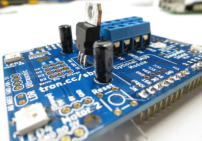
All of these components need to be oriented correctly, and can be damaged if you fit them backwards. Place the regulator as shown, with the large metal tab facing towards the screw terminals.
Electrolytic capacitors have a grey stripe on the side marked "-", which is the negative side. The circuit board has a small plus marked next to the pin for the positive side. Both the positive sides face towards the regulator, as shown, so the capacitors are "mirrored" in orientation to each other.
You can bend the pins on the capacitors and the regulator to make them stay in while you solder them, or use Blu-Tac.
After they are soldered you can cut the leads off. Make sure you hold the lead while you cut it, so that it doesn't shoot off like a tiny metal javelin straight into your eye:
LDR, Range Sensor Header, Servo Headers
Next step is the LDR (light dependent resistor), the 4-pin female header for the Ultrasonic Range Sensor, and the two 3-pin male headers for the "Motors" (actually continuous rotation hobby servos, not normal motors).
For the 3 pin headers, cut them from longer male header strips if they haven't been pre-cut.
Place the parts into the PCB as shown. Orientation doesn't matter with these parts.
It's recommended you leave LDR sitting high above the PCB surface, as shown, so you can bend it forwards 90 degrees to create a directional light sensor.
The LDR can be soldered from the top or the bottom, but the header needs to be soldered from the bottom. Use Blu-Tac or your finger to hold items in place when flipping the board.
Wire AREF to 5V
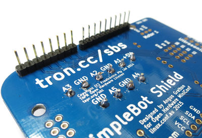
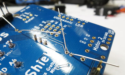
There's a flaw in the current SimpleBot Shield design: the LDR is connected to the "AREF" pin on the shield when it should be connected directly to "5V".
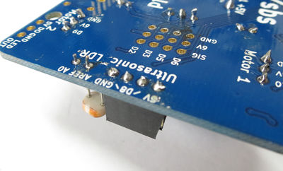
To fix this problem, solder a quick fix from the AREF pin on the shield to either the "5V" pin or the "IORef" pin on the shield. You can use the wire wrap wire in the kit, or the cut off leg of a resistor or another component.
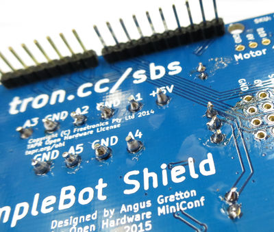
Once you've done this, cut off the "AREF" pin on the shield to disconnect from AREF on the PiLeven:
Reset Button & Resistor
The 10k resistor forms a voltage divider with the LDR in order to output a voltage proportional to the ambient light level.
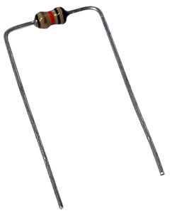
Bend the leads of the resistor so that it slips neatly into the holes on the PCB:
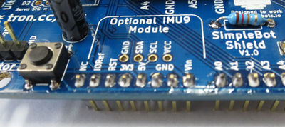
The resistor and the reset button can be soldered from the top or the bottom, as you prefer. If soldering the reset button from the top, take care not to melt the plastic body of the button.
All Done
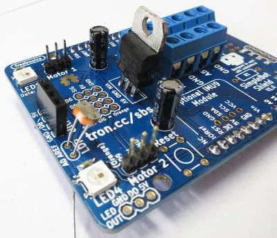
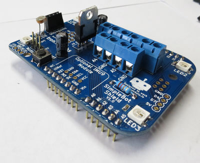
All done! As a final check, look over the shield for any solder bridges and also double-check the that the regulator and the electrolytic capacitors aren't installed backwards:
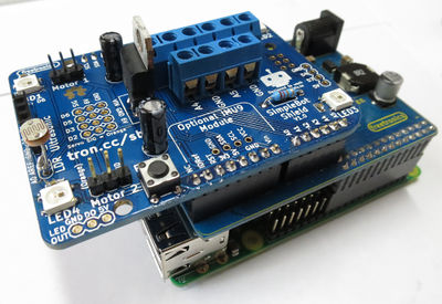
Here's a photo showing how the SimpleBot shield mounts onto the PiLeven:
Next step, you can move on to SimpleBot Chassis Assembly.
