SimpleBot Battery Pack Assembly: Difference between revisions
No edit summary |
No edit summary |
||
| (3 intermediate revisions by the same user not shown) | |||
| Line 8: | Line 8: | ||
[[File:SimpleBot-battery-pack-1.jpg|480px]] | [[File:SimpleBot-battery-pack-1.jpg|480px]] | ||
Unscrew the black plastic cover on the 2.1mm DC jack. | Unscrew the black plastic cover on the 2.1mm DC jack. Use a soldering iron to "tin" the metal tabs on the back of the DC jack. This means heating up the tab and placing a small blob of solder on the tab in preparation for making a joint: | ||
[[File:SimpleBot-battery-pack-2.jpg|480px]] | |||
Insert both the battery holder wires through the plastic cover. Important: you must do this before anything else! It's a common mistake to miss this step, then have to unsolder everything and start again. Solder the '''black''' wire to the longer tab that connects to the outside of the DC jack, then use a pair of pliers to bend over the anchor tabs to mechanically hold the wire in place: | |||
[[File:SimpleBot-battery-pack-3.jpg|480px]] | |||
Slip the heat-shrink tubing over the '''red''' wire, and then solder the wire to the shorter tab that connects to the centre of the DC jack | Slip the heat-shrink tubing over the '''red''' wire, and then solder the wire to the shorter tab that connects to the centre of the DC jack: | ||
[[File:SimpleBot-battery-pack-4.jpg|480px]] | |||
Touch the side of the soldering iron tip (not the end of the tip) on the heat-shrink tubing to make it shrink onto the joint and hold firmly in place | Slide the heat-shrink tubing along the red wire to cover the solder joint and terminal, to prevent any possibility of a short circuit between the terminals. Touch the side of the soldering iron tip (not the end of the tip) on the heat-shrink tubing to make it shrink onto the joint and hold firmly in place: | ||
Screw the plastic cover back onto the DC jack. | [[File:SimpleBot-battery-pack-5.jpg|480px]] | ||
Screw the plastic cover back onto the DC jack: | |||
[[File:SimpleBot-battery-pack-6.jpg|480px]] | |||
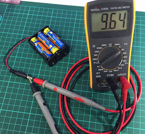
Before using the battery pack, it's a good idea to check that it's providing the right voltage but particularly the correct polarity. If you made a mistake and connected the wires the wrong way around it could damage your PiLeven board. | |||
The centre of the DC jack should be positive and the outside of the DC jack should be negative. You can check this using a multimeter set to a suitable DC voltage range, by placing the red (positive) probe into the centre of the DC jack and touching the black (negative) probe to the outside. You should see a voltage of around +9V. If you see a negative value, unscrew the back cover from the DC jack and make sure you have the red and black wires going to the correct tabs: | |||
[[File:SimpleBot-battery-pack-7.jpg|480px]] | |||
[[SimpleBot-Assembly|Back to SimpleBot Assembly Overview]] | |||
Latest revision as of 07:00, 10 January 2015
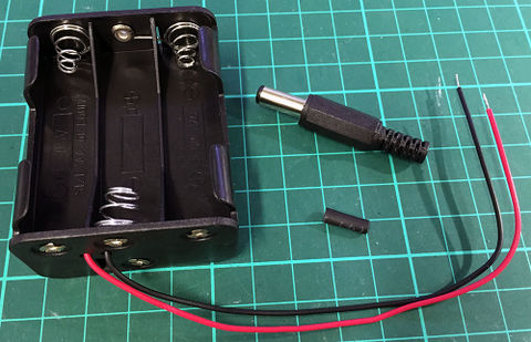
Assembling the battery pack requires 4 parts:
- Battery holder
- 2.1mm DC jack
- Heat-shrink tubing
- 6 x 1.5V AA cells
Unscrew the black plastic cover on the 2.1mm DC jack. Use a soldering iron to "tin" the metal tabs on the back of the DC jack. This means heating up the tab and placing a small blob of solder on the tab in preparation for making a joint:
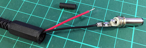
Insert both the battery holder wires through the plastic cover. Important: you must do this before anything else! It's a common mistake to miss this step, then have to unsolder everything and start again. Solder the black wire to the longer tab that connects to the outside of the DC jack, then use a pair of pliers to bend over the anchor tabs to mechanically hold the wire in place:
Slip the heat-shrink tubing over the red wire, and then solder the wire to the shorter tab that connects to the centre of the DC jack:
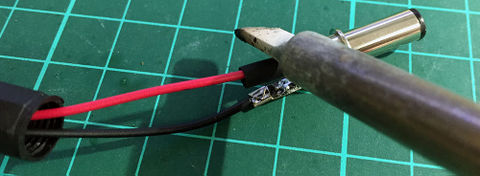
Slide the heat-shrink tubing along the red wire to cover the solder joint and terminal, to prevent any possibility of a short circuit between the terminals. Touch the side of the soldering iron tip (not the end of the tip) on the heat-shrink tubing to make it shrink onto the joint and hold firmly in place:
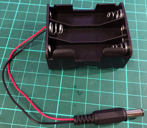
Screw the plastic cover back onto the DC jack:
Before using the battery pack, it's a good idea to check that it's providing the right voltage but particularly the correct polarity. If you made a mistake and connected the wires the wrong way around it could damage your PiLeven board.
The centre of the DC jack should be positive and the outside of the DC jack should be negative. You can check this using a multimeter set to a suitable DC voltage range, by placing the red (positive) probe into the centre of the DC jack and touching the black (negative) probe to the outside. You should see a voltage of around +9V. If you see a negative value, unscrew the back cover from the DC jack and make sure you have the red and black wires going to the correct tabs:
