LoliBot Assembly
Tools
Your own tools are not required for the Open Hardware Miniconf assembly session, but if you are able to bring any of the following then that would be great.
If you're flying, please bear in mind that sharp items like cutters or multimeter probes will need to be put into checked baggage not carry-on.
- Wire cutters (and wire strippers if you have them)
- Multimeter
- Soldering iron
- Solder
Check Parts In Kit
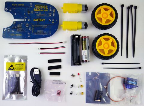
Your kit should contain the following items:
Your kit will also include an extra cable tie and a 3-way 90-degree header, which aren't shown in the picture above.
Please check over the items in your kit, and if you think you are missing something then let us know.
Step 1: Install power LED
If this is your very first time soldering, please ask an instructor to help you with this step.
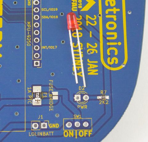
The power LED is a small red part with two leads. Here you can see it sitting on the LoliBot PCB just near the position where it will be installed:
Look carefully at the legs of the LED. You will notice that one of the legs is longer than the other. Also, there is a small flat section on the body next to the shorter leg. LEDs are "polarised", which means they need to be installed the right way around. If you install it backward, it won't work.
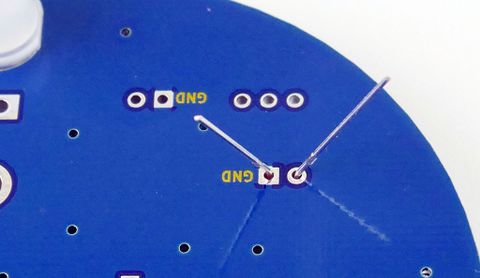
Insert the LED into the PCB with the pins oriented as shown above. Then, hold the body of the LED against the PCB while you gently bend the legs apart underneath the board, so that it is held in position and can't fall out:
When you turn the PCB over, you should see that the shorter lead goes through the hole marked "GND".
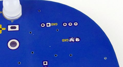
Now, solder both leads of the LED to the pads on the circuit board. Then use side-cutters to trim the component leads just above the solder joint:
WARNING! The leads can shoot off like tiny steel javelins when they are cut. Make sure you hold the leads with one hand while you cut them with the other. Don't let them fly around the room, and make sure you collect all the offcuts to dispose of later. Please show respect for the venue by avoiding leaving offcuts lying around at the end of the assembly session.
Step 2: Install power switch
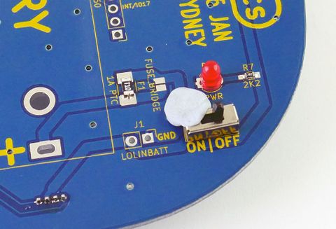
The power switch has three pins, and mounts just near the power LED. The switch is NOT polarised, which means it doesn't matter which way around you install it. It works the same both ways.
The switch may fall out when you turn over the PCB to solder it, so one trick is to use a little blob of blu-tac to hold it in place:
Step 3: Install JST sockets
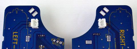
Two JST sockets need to be mounted near the motor locations. The sockets have a slot down one side, so be careful to align them with the slots pointing towards each other as shown in the photo:
Just like the switch, you might find that a blob of blu-tac is a big help keeping them in place during soldering.
Step 4: Install IMU socket
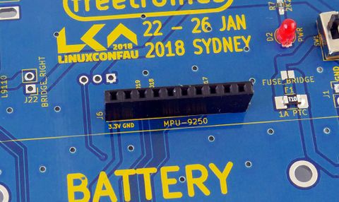
The IMU (Inertial Measurement Unit) is supplied as a separate module that can be plugged into the robot chassis. Insert the black 10-way socket into the PCB as shown, and hold it in place with blu-tac while you solder it from the bottom:
Step 5: Install IMU headers and module
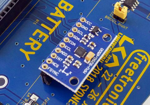
Inside the pack for the IMU is a 10-way pin header. The easiest way to fit it to the IMU module is to use the IMU socket to hold everything in place. The pin header has longer pins on one side and shorter on the other. Insert the longer pins into the socket on the robot, then fit the IMU module onto the shorter pins on top:
Now solder the pin header to the top of the IMU module PCB.
After it has been soldered in place, you can remove and re-insert the IMU module if necessary.
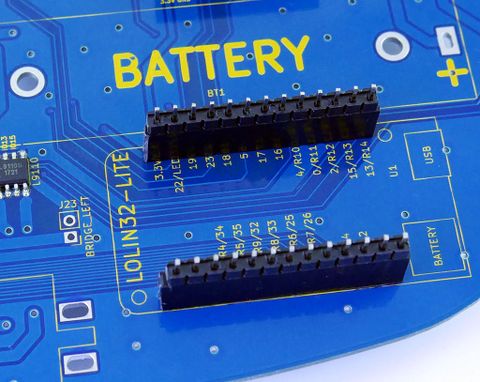
Step 6: Install Lolin32-Lite sockets
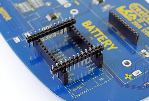
Installing the sockets for the Lolin32-Lite is very similar to the socket for the IMU, and you can do it the same way if you like. However, a good trick is to use the pin headers for the Lolin32-Lite as guides to keep the sockets aligned. Place the sockets in the PCB, and then insert the pin headers sideways as shown here:
Then solder the sockets in place.
Step 7: Install Lolin32-Lite headers and module
Just like with the IMU, insert the pin headers into the sockets with the longer side of the pins inserted:
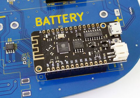
Then fit the Lolin32-Lite onto the pins:
Solder the pin headers to the top of the Lolin32-Lite.
Step 8: 2-way pin headers
Insert the pair of 2-way pin headers into the PCB as shown, and hold in place with blu-tac:
These headers can be a little bit loose, and they may not sit straight in the holes. Try to keep them straight while you are soldering them.
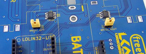
Step 9: Fit header jumpers
Place the two yellow jumpers onto the pin headers you just installed:
Step 10: Attach Lolin32-Lite power lead
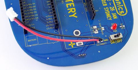
In the kit are parts there are three red/black leads with JST plugs fitted. One of them is longer than the others. This is the power lead for the Lolin32-Lite. You can install it as supplied, but it's longer than required to reach the Lolin32-Lite power socket so you can cut it shorter if you like. Check the photo below to see where it will go:
IMPORTANT: This lead is the reverse polarity to the other two JST leads, so don't get them mixed up if you cut it shorter!
If you cut the lead shorter, use a pair of side-cutters to trim about 5mm of insulation from the end of the wires. Then twist the tiny strands of wire together, then use the soldering iron and solder to "tin" the leads, which means to apply some solder without attaching it to anything. This keeps all the strands joined together and helps you solder the wires to the PCB.
Step 11: Install servo header
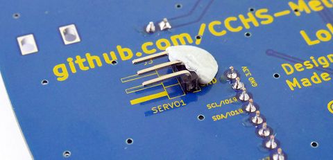
All the parts that you have installed so far have been on the top of the PCB. The servo header is the small 3-way pin header with a 90-degree bend, and it needs to be installed from the bottom of the PCB instead. Turn the PCB over, find the markings to show the orientation, and insert the shorter end into the PCB:
Because it is bent at a 90 degree angle, the header will sit parallel to the PCB.
Step 12: Install battery holder
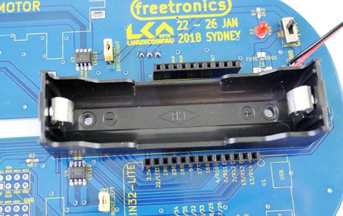
IMPORTANT: The battery holder can physically fit either way around, but it's critical for the battery to be installed with the correct polarity. If you look carefully inside the battery holder you will see little "+" and "-" symbols moulded into the plastic. Make sure you orient the holder so that the + and - symbols match up with the markings on the PCB, then solder it from underneath:
Step 13: Attach motor leads
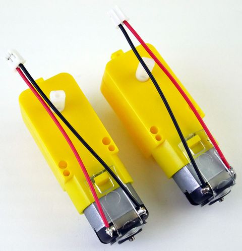
The two shorter red/black leads with JST plugs are the correct length for the motors. Place the motors on the bench as shown below, and use the soldering iron to tin the little tabs on the motors. Then lay the leads on top and solder them to the tabs:
IMPORTANT: In the picture you can see that the leads have opposite orientation. This is to ensure that the motors both turn in the same direction when they are attached to the robot.
Step 14: Attach motors
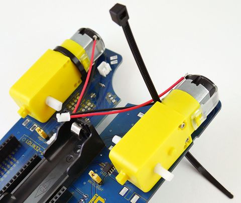
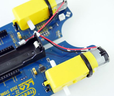
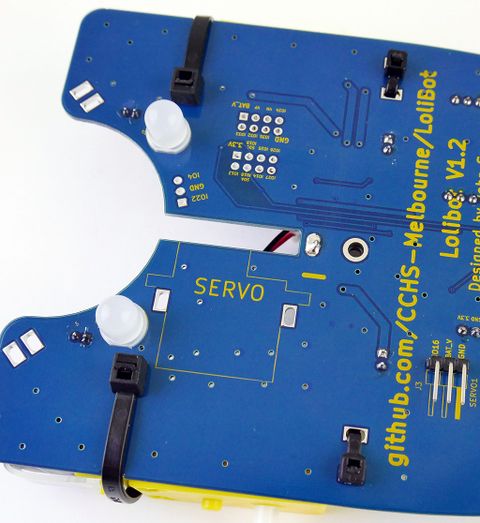
The motors are attached to the LoliBot chassis using two cable ties each. A large cable tie goes around the body of the motor, and a small cable tie goes through the tab on the back of the motor:
Step 15: Plug in motors
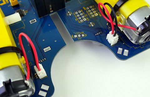
The motor leads plug into the JST sockets next to each motor:
